Languages:


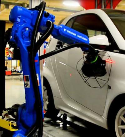
LaserGauge® Automation is a robotic system for measuring vehicle gap/flush on a moving assembly line. It is cost-effective, fast, flexible, and delivers LaserGauge® accurate measurements.
Utilizing the Cross-Vector scanning technology, the LaserGauge® Automation System provides more surface information around the edges of assembled panels than any other robotic laser profiler. This is particularly important for accurate gap and flush measurements.
The system is flexible. Measurement routines are developed using the LGWorks software. Measurement locations for each vehicle are taught to the robot. Implementation is completed in a matter of days, not weeks.
The Automation software can be used with any brand of robot, and can support 2, 4, or more robots at the same time. It can be installed by an outside integrator or the plant’s personnel.
Advanced Cross-Vector Measurement Sensor

The most innovative feature of the Automation system is the advanced Cross-Vector scanning sensor. Traditional laser profilers utilize a single laser stripe coupled with a single imager to capture surface scans. But a single view does not reveal surface points around the radius on the edge of the gap.
The Cross-Vector sensor utilizes multiple lasers and multiple views at crossing angles. This allows the sensor to see around edges of the radius to the vertical tangent and beyond. The result is a complete surface profile and the most accurate gap measurements. This provides a higher density of points around the edges for increased accuracy and repeatability. No sensor movement or rolling of the sensor is required. The sensor is automatically positioned into non-contact alignment for each scanning location based on real-time feedback from the vehicle position and orientation detection systems.
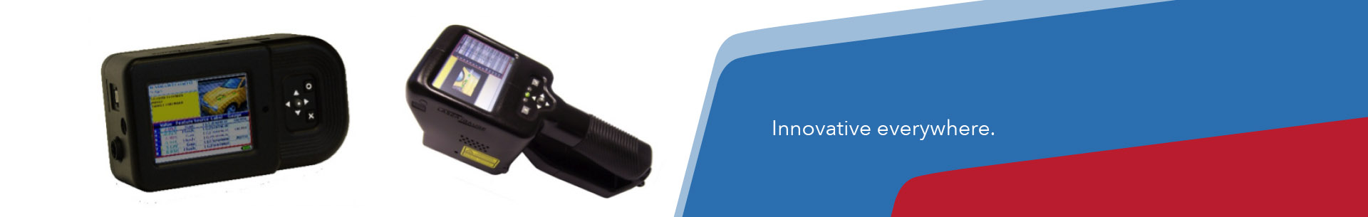
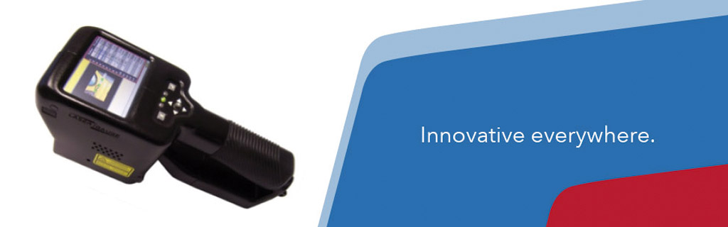
Proven LaserGauge Capabilities

The LaserGauge® line of handheld inspection sensors has been serving automobile manufacturers for 15 years. The LaserGauge® Automation continues that functionality with an automated gap/flush inspection system that is 100% compatible with the measurement methodologies (Virtual Gauges) of other LaserGauge® products.

Inspection routines are created and edited using the LGWorks software. Virtual Gauges are configured specifically for each measurement point and specification limits are defined for each returned value. Detailed graphics and on-screen messages indicate the location and progress of the robotic sensor from one measurement to the next. Complex calculations referencing measurement data can be processed in the routine and included in the data file. All scans and numerical data can also be saved and output to various formats, pushed directly into the plant’s data handling system, and/or passed to a Fitter’s Station for manual refit of panels.
Flexible Robot Interface

Flexibility and ease of setup has been designed into the system. The Automation software and the robot controller use two-way communications to control sequencing and operation. Use of an “AnyBus Communicator” allows easy integration with any robot (ABB, Fanuc, Yaskawa, Kuka, etc.) and a special TEACH MODE allows quick and easy sensor location on any vehicle. Development tools are available from Origin Technologies Corporation for third-party integrators or for the plant’s robot programmers to implement and support the system internally. Virtualization tools allow for the testing of the system before installation is complete.
Real-Time Vehicle Position/Orientation Tracking and Path Correction
As the vehicle moves into the LaserGauge® Automation station, the system receives the VIN and that is used to identify the model of vehicle. Data from the vehicle detection and positioning/orientation systems along with specific design information for that model are fed into the Automation software. The robot path is corrected based on this vehicle-specific data. Real-time robot path changes allow the robot to accurately position the LaserGauge® sensor at the correct location even though the vehicle is moving or is in a different orientation/position than when the measurement point was first taught to the robot. Multiple safeguards are embedded into the system to prevent the robot from colliding with the vehicle:
Fitters Module
The Fitter’s Module accumulates and filters the measurement results from a LaserGauge® Automation station and then displays the results on a separate monitor for the manual refitting of out-of-spec parts. The fitter can use a handheld LaserGauge® inspection system for a secondary inspection or for confirmation. Rescanned data can be logged and passed to the factory’s data handling system or it can be archived. The Fitter’s module software runs on a separate PC from the LaserGauge® Automation station.
ADVANTAGES
Complete Surface Profile – The Cross-Vector approach captures surface profiles around edges and down into the gap. This results in the most complete surface profile and most accurate measurements from a single scan. No need for multiple measurement sensors or rotational scanning motion to acquire a complete scan.
Speed – The scanning process is completed, measurements calculated, results displayed in the data table, and the scan plotted on the graph, all in less than one second. The non-contact sensor is able to move from point to point while the assembly line is in motion.
Cost – The LaserGauge® Automation system is more cost effective than other robotic systems. Use of plant preferred integrators or internal resources to install the system, the flexibility of the Automation software, and the ease of setup/implementation all help to reduce the overall cost of the system.
Flexibility – Points can be added and deleted from existing routines, and new routines can be added using the TEACH MODE, without having to involve the robot programmers. The LaserGauge® Automation system supports 1, 2, 4, or more robots.
Compatibility – All routines, virtual gauge definitions and, data output capability are 100% compatible with all other LaserGauge® products.
jotbe Systemhandel GmbH
Dreyer Straße 6-8
28844 Weyhe
Phone: +49 (0) 4203 - 44 00 -0
Fax: +49 (0) 4203 - 44 00 -10
E-Mail: info@jotbe.com
Our new catalog reached us today. You can download the catalog in two languages directly here at our webpage: LaserGauge brochure / english version LaserGauge Broschüre /... more